
Duct specifications are critical parameters in the design and installation of ventilation and air conditioning systems, directly affecting airflow delivery, pressure loss, and spatial layout. The following provides a detailed explanation of common types, size standards, and selection criteria:
1. Classification of air ducts by material and specification characteristics
Different types of ductwork vary in terms of material, specifications, and applicable scenarios:
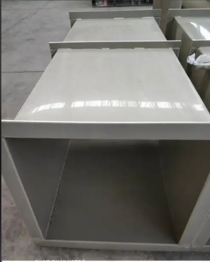
Galvanized steel sheet ductwork
Thickness: Determined based on duct dimensions, commonly ranging from 0.5mm to 2.0mm (e.g., for rectangular ducts with a long side ≤320mm, thickness is 0.5mm; for long sides between 1600mm and 2000mm, thickness is 1.2mm).
Size range:
Rectangular ducts: Long sides typically range from 120mm to 2000mm, with corresponding short sides from 60mm to 1250mm (e.g., 320×200mm, 800×400mm, etc.). Larger
sizes require customization.
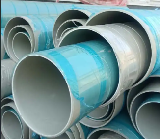
Round ducts: Diameter generally ranges from 100mm to 1600mm (e.g., φ150mm, φ800mm, etc.), with extra-large diameters requiring welding.
Fiberglass ductwork
Dimensions: Rectangular ducts can be up to 3000 mm long, circular ducts can be up to 2000 mm in diameter, with wall thicknesses ranging from 5 mm to 10 mm. These ducts are corrosion resistant but relatively heavy, making them suitable for use in humid environments.
Stainless steel ductwork
Dimensions: Similar to galvanized steel ductwork, but thicker (generally 0.8 mm to 3.0 mm), suitable for clean rooms, food processing plants, and other locations requiring corrosion resistance.
2. Duct Dimension Notation Rules
Rectangular ducts: denoted as “long side × short side” (unit: mm), e.g., “500×320mm” indicates a long side of 500mm and a short side of 320mm.
Round ducts: Denoted as “diameter φ + numerical value,” e.g., “φ300 mm” indicates a diameter of 300 mm.
Dimension tolerances: National standards permit ±1 mm to ±3 mm (depending on size) to ensure connection sealing integrity.
3.Selection Criteria for Duct Specifications
Air flow Requirements: The cross-sectional area of the duct is related to the air velocity. The calculation formula is: Airflow (Q) = Cross-sectional Area (A) × Air Velocity (v) × 3600 (Unit: m³/h)
Air velocity must be reasonable (e.g., main duct air velocity in HVAC systems: 8–12 m/s; branch ducts: 3–6 m/s). Excessively high air velocity can cause excessive noise and resistance, while excessively low air velocity may result in overly large duct dimensions.
System Pressure: High-pressure systems (>1500 Pa) require thicker panels and reinforcement measures; duct dimensions should not be too large. Low-pressure systems (≤500 Pa) can use thinner panels.
Installation Space: Constrained by building ceiling height, beams, etc., duct dimensions must be balanced with spatial layout (e.g., rectangular ducts are preferred in narrow spaces to save height).
4.Notes
Duct specifications must comply with the “Code for Acceptance of Construction Quality of Ventilation and Air Conditioning Engineering” (GB 50243) to ensure strength and airtightness.
Non-standard ducts (e.g., elliptical) must be custom-made, with specifications calculated based on equivalent cross-sectional area.
Large-sized ducts (long side > 2000 mm) must be equipped with reinforcing ribs to prevent deformation.
Selecting appropriate duct specifications can ensure system performance while reducing costs and installation complexity.